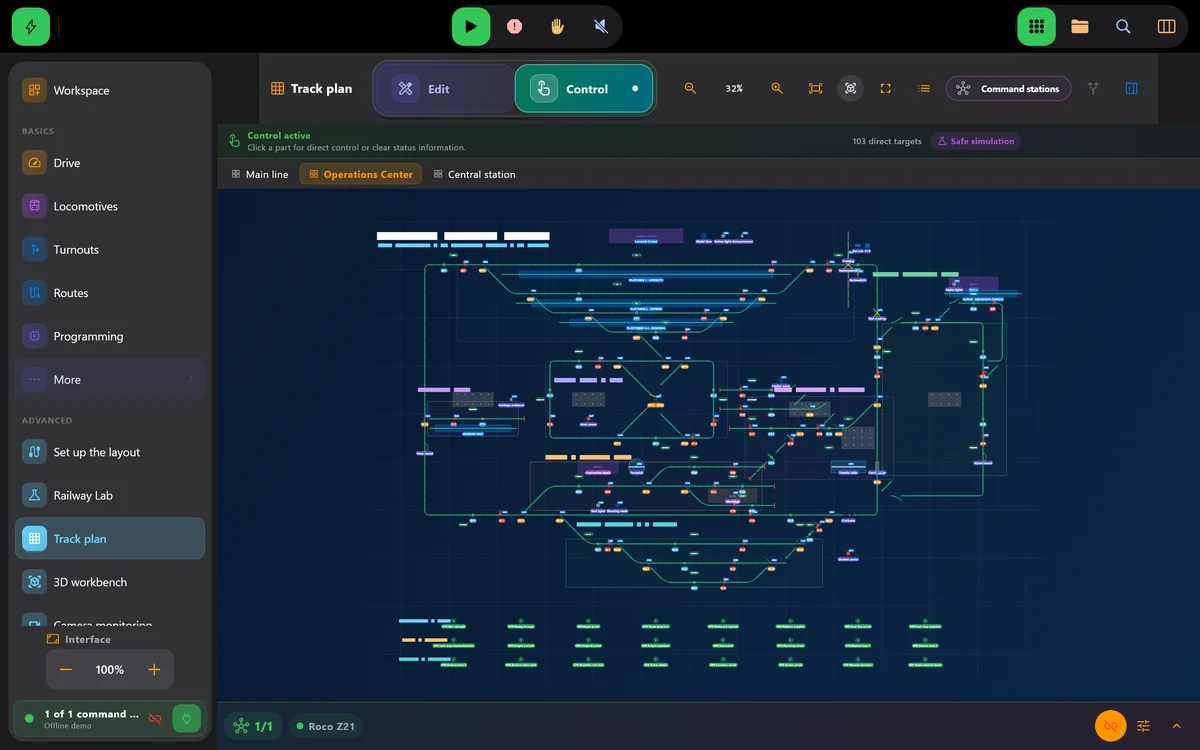
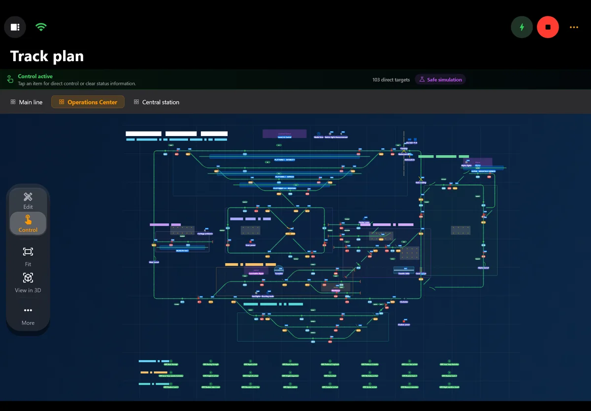
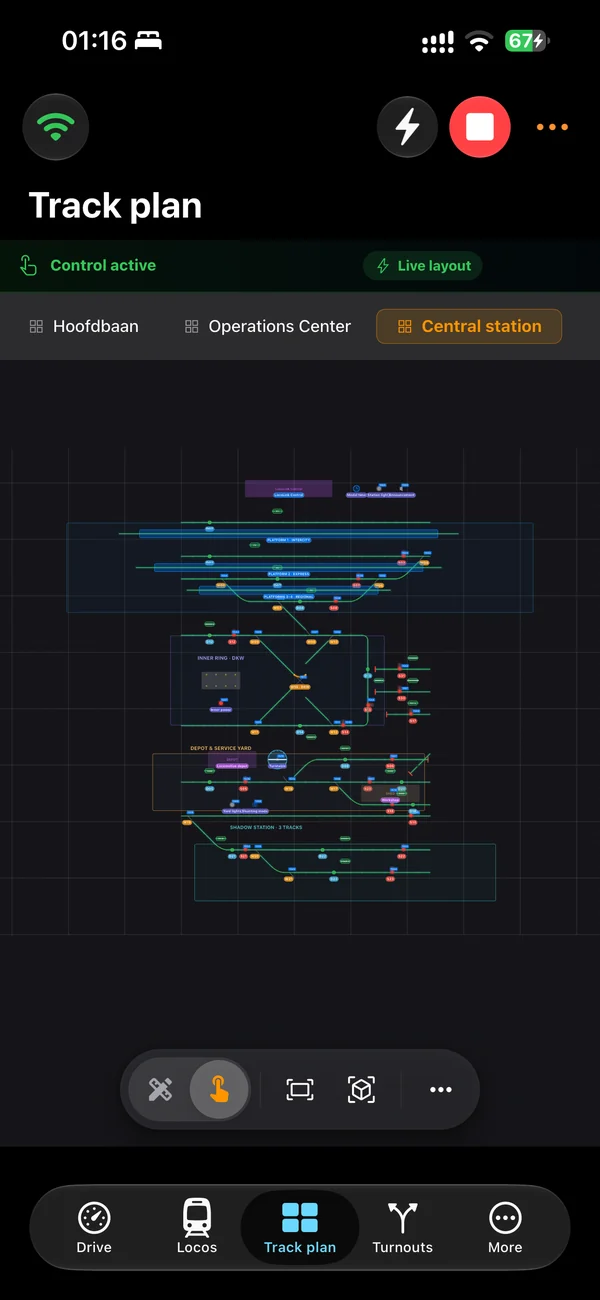
Operational track plan
This is a control diagram for real turnouts, signals and feedback—not general CAD or 3D layout-design software.
Real LocoLink product video · 3:06
Watch the actual LocoLink 1.7.9 desktop app create a track plan, place turnouts and feedback, assign DCC addresses and switch from drawing to live layout control.
Real LocoLink 1.7.9 desktop capture. This is publisher-created product footage, not an independent review or a recording of live command-station hardware.
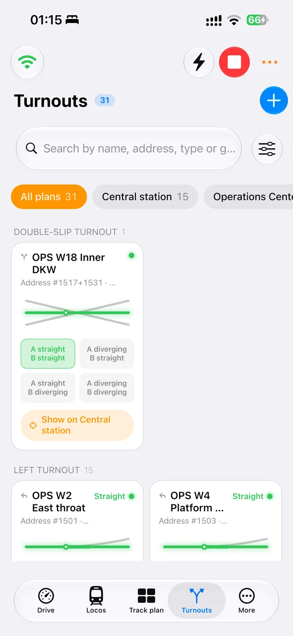
Real screens of LocoLink 2.0 on Windows, Mac, iPad and iPhone.
Jump to a step
Select a chapter to move the real product recording to that exact step.
What the recording proves
This is a control diagram for real turnouts, signals and feedback—not general CAD or 3D layout-design software.
The tutorial shows where DCC accessory addresses and a second decoder address are configured before Control mode sends commands.
Edit mode builds and configures the diagram. Control mode turns the same drawing into an operating switchboard.
Blocks and occupancy feedback can be added after manual turnout and signal operation has been verified.
Searchable transcript
The text below follows the spoken recording and keeps every demonstrated step accessible without playing audio.
Build a Track Plan from scratch in the LocoLink desktop app, connect interactive railway elements and move from editing to live control.
Open Track Plan from Layout and create a clean tab for a station, staging yard or another part of the railroad.
Edit mode places and configures elements; Control mode turns the completed diagram into an operational switchboard.
Choose straight, curved, diagonal and linking pieces, place them on grid cells and rotate them to match the layout.
Place left, right, crossing, double-slip and three-way turnout geometry where the real railroad branches.
Signals and occupancy feedback sensors use the same visual placement workflow.
Set labels, rotation and DCC addresses; use a second turnout address when the decoder requires it.
Control mode sends configured turnout and signal commands and warns when an address is missing.
Use zoom, pan, fit-to-layout, labels, a minimap, diagnostics and separate track-plan tabs.
Link track sections and feedback so free, reserved and occupied states appear directly on the plan.
Create, draw, configure, verify and operate the model railroad from one LocoLink workspace.
FAQ
No. The Track Plan in LocoLink is an operational control diagram for real turnouts, signals, feedback and blocks. It is not general-purpose CAD or 3D layout-design software.
Yes. It is a real LocoLink 1.7.9 desktop capture. The recording is created by the publisher and is not presented as an independent review.
Yes, after the supported command-station connection and the correct accessory addresses have been configured and verified. The video shows where those addresses are entered.
No. Start with one small test area, confirm manual train and turnout control, and add feedback, blocks and automation in stages.
LocoLink fully supports the command stations listed in its compatibility adviser, including Z21, ECoS, DCC-EX, NCE and Märklin CS3 connection routes.
Verification
This watch page and recording are published by LocoLink. Product requirements and compatibility are linked to the current first-party pages; no independent review is claimed.